
I’ll try the tip with the led, but that will take a while cause I will need to solder a little bit.Įdit: Regarding my guess: I meant, if I switch the ground (with a physical switch, the optoisolator not in my circuit) they still runĮdit2: I found out something rather interesting while testing out with the LED, if I disconnect my fan I get the correct 12V. If I read the Datasheet corretly (I’m not so sure :/) it can handle a voltage up to 70V (the Collector emitter breakdown voltage, or for what voltage would I need to look?) I looked at the SparkFun website and I didn’t see a current spec and I didn’t see what transistors they are using.

I’d be surprised if that thing can power a fan. I drew a Schematic, hopfully it gets more clear with that. I’ not going to try and draw one or visualize the circuit from your description. The 12V on the output-side is separate (and possibly isolated depending how it's wired-up). (My guess is thats because of the voltage difference between 5v PWM signal and the 12v Power Supply.)ĥV is enough to turn-on the LED inside the opto-isolator. If the LED does work, leave the LED attached and connect the motor. If the LED isn't switching on & off, stick the LED (with resistor) on the input-side of the opto-isolator to make sure it's getting a pulse. Try the Blink Example modified for whatever I/O pin you're using. Try replacing the motor with an LED (with the usual current-limiting resistor). At this point the transistors (and maybe the opto-isolators) may be fried from excess current or from the back-EMF from the fan motor (since you didn't add a flyback-diode and there isn't one on the board). I looked at the SparkFun website and I didn't see a current spec and I didn't see what transistors they are using.

I'd be surprised if that thing can power a fan. I' not going to try and draw one or visualize the circuit from your description. On the input side I connected ground to the Arduino Ground and the Inputs to two seperate digital Pins
#Ttl optical isolator sparkfun free#
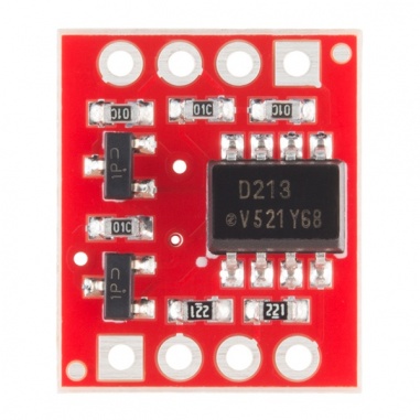
If you need to know anything else, feel free to ask. So my question is: What did I do wrong that I got these off voltages? I measured on the input side 4.4V on both channels when I set the digital Pins to High. On the input side I connected ground to the Arduino Ground and the Inputs to two seperate digital Pins. HV to the 12V+ of the power supply and the outputs to the VCC inputs of the fans. I connected HVG of the breakout board with the ground of the fans and my power supply. Here the link to the board: Sparkfun OptoisolatorĪnd the used Isolator on the board is the ILD213T. In general it works (if no signal from the Arduino is sent, I also get 0V output), but if I use a digitalWrite(Pin, HIGH) to send the switching signal I get on the one channel 0.9V and on the second 1.1V. So I used a optoisolator breakout board from Sparkfun to switch my 12V+. (My guess is thats because of the voltage difference between 5v PWM signal and the 12v Power Supply.)īut if I switch the 12V+ they shut off (with a physical switch). I've built a fan controller with PWM, and now I want to be able to switch them completly off, cause I've got a watercooling loop.įor some reason, if I switch the ground of the fans, they still run.

I'm trying to switch a 12v voltage with my Arduino.


 0 kommentar(er)
